Structure: Burj al Arab
Location: Dubai, United Arab Emirates
Architect: W.S. Atkins and Partners
Structural Engineer: Eversendai Engineering
Construction: Al Habtoor Engineering
Murray and Roberts
Fletcher Construction
Date: 1994-1999

"If you can draw a building with a few sweeps of the pen and everyone recognizes not only the structure but also associates it with a place on earth, you have gone a long way towards creating something iconic."
-Tom Wright
Architect of the Burj al Arab, 2000
Part 1 Overview
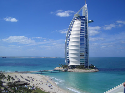
The Burj al Arab, or "Tower of the Arabs," is the iconic structure located in the United Arab Emirates on the Arabian Peninsula. What the Eiffel Tower is to Paris, the Burj al Arab is to Dubai. Designed to resemble an Emirate dhow, or sailing vessel, by Tom Wright of Atkins and Partners, 'The Burj' is the largest single-standing hotel in the world, reaching 1,053 ft.


Renderings
When each of these nested families were loaded together into a project file, you can see the structure come together in the mental ray renderings below.


When attempting to place the trusses in their correctly angled orientations, Revit would only allow rotation of the instance about the plane or axis in which it was created. I needed to rotate the truss about a different axis, which it would not allow. To resolve this, I created three small angle blocks to serve as faces in which to place one end of the truss when loaded into the larger family.
Another limitation I encountered occurred when modifying nested families. When attempting to modify a family nested within another family or project, there were several instances in which the nested family was inaccurately altered or corrupted by the program once it opened. Also, regardless of the computer I was using, the load time was fairly lengthy. To avoid these issues, I had to directly open the appropriate family file I wanted (rather than through the Revit interface), made the needed modifications, then reloaded it back into the larger family or project. This saved load time, as well kept the file integrity intact. For most projects, the load time probably isn't much of an issue; however, this structure had families, each of which contained nested families several layers deep.
Part 2 Overview
The focus of Project 2 was to alter parameters found in the Revit model using computer programming to aid in the creation of multiple design scenarios.
Changes
First, two new parameters were added at the project level, under "Project Information." One parameter is an integer-driven parameter named "Time of Day," and the other additional parameter is text-driven and is named "WeekDay."
In addition, several exterior floodlight instances were added throughout the model.
Transparency of Exterior Facade
One goal was to alter the transparency of the front facade of the building model based on the time of day. In an effort to save on energy costs, both in terms of cooling and interior lighting, the front facade is to filter out more sunlight and heat during the hottest parts of the day and allow more sunlight and heat during the coolest parts of the day.
Using the Time of Day parameter found in the Project Information tab, the user inputs the hour of the day, from 0 to 23.

The coding pulls from an external database to find a corresponding Transparency value, which is then applied to the front screen facade of the structure model.


Location: Dubai, United Arab Emirates
Architect: W.S. Atkins and Partners
Structural Engineer: Eversendai Engineering
Construction: Al Habtoor Engineering
Murray and Roberts
Fletcher Construction
Date: 1994-1999
"If you can draw a building with a few sweeps of the pen and everyone recognizes not only the structure but also associates it with a place on earth, you have gone a long way towards creating something iconic."
-Tom Wright
Architect of the Burj al Arab, 2000
Part 1 Overview
The Burj al Arab, or "Tower of the Arabs," is the iconic structure located in the United Arab Emirates on the Arabian Peninsula. What the Eiffel Tower is to Paris, the Burj al Arab is to Dubai. Designed to resemble an Emirate dhow, or sailing vessel, by Tom Wright of Atkins and Partners, 'The Burj' is the largest single-standing hotel in the world, reaching 1,053 ft.

Allaboutskyscrapers.com
Modeling Process
The very features that make The Burj so iconic, such as its flying buttresses, cantilevered restaurant, mast spire, helipad, and translucent facade, also made it challenging to model. Revit Architecture 2012 was the building information modeling (BIM) software used to create the following model.
Mass Form
The unique sail shape of the structure was modeled by creating three parametrically-driven footprints at the lower, mid, and upper levels of the building. These three shapes were then swept and blended into one mass form.

Mass Form
Bracing
The exterior bracing, or buttresses, were created through a series of nested families. These families include the rear support columns, the 'flying' front buttresses, the horizontal braces, and the angled space trusses used for lateral bracing. Each of the these families are parametrically driven. An interesting note to point out - the scale of this structure is incredibly deceptive because the background is the vast Persian Gulf. Each of the six diagonal space trusses are longer than a soccer field!

Bracing
Distinguishing Geometry
Other than the overall shape of the structure, the two most distinguishing exterior features of The Burj are the helipad located on the front face of the structure near the roof level and the cantilevered restaurant located opposite on the rear face. Both the helipad and restaurant are nested families loaded into the larger mass model family. Once again, both are defined by adjustable parameters.

Helipad
Facade
The facade of the structure has glazed curtain wall on three of the building's faces, the front face being curved. These curtain walls were modeled usiing rectangular curtain wall surface patterns with custom curved horizontal and vertical mullions defined within the pattern. The front of the structure also has a translucent screen which not only provides unique aesthetics, but also filters the intense Arabian sun and the heat that comes with it.

Front Facade
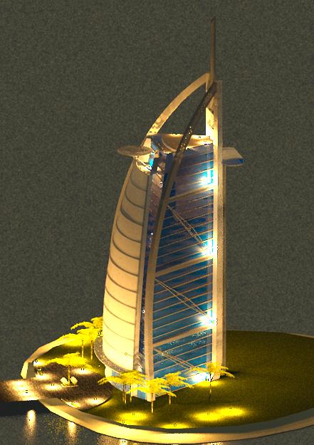
Renderings
When each of these nested families were loaded together into a project file, you can see the structure come together in the mental ray renderings below.

Exterior Rendering

Interior Rendering
Critique
Overall, the Revit user interface proved very efficient and user-friendly in modeling such a geometrically complex structure. The three-dimensional views proved quite helpful when orienting the various elements. A few drawbacks to note:When attempting to place the trusses in their correctly angled orientations, Revit would only allow rotation of the instance about the plane or axis in which it was created. I needed to rotate the truss about a different axis, which it would not allow. To resolve this, I created three small angle blocks to serve as faces in which to place one end of the truss when loaded into the larger family.
Another limitation I encountered occurred when modifying nested families. When attempting to modify a family nested within another family or project, there were several instances in which the nested family was inaccurately altered or corrupted by the program once it opened. Also, regardless of the computer I was using, the load time was fairly lengthy. To avoid these issues, I had to directly open the appropriate family file I wanted (rather than through the Revit interface), made the needed modifications, then reloaded it back into the larger family or project. This saved load time, as well kept the file integrity intact. For most projects, the load time probably isn't much of an issue; however, this structure had families, each of which contained nested families several layers deep.
Part 2 Overview
The focus of Project 2 was to alter parameters found in the Revit model using computer programming to aid in the creation of multiple design scenarios.
First, two new parameters were added at the project level, under "Project Information." One parameter is an integer-driven parameter named "Time of Day," and the other additional parameter is text-driven and is named "WeekDay."
In addition, several exterior floodlight instances were added throughout the model.
Transparency of Exterior Facade
One goal was to alter the transparency of the front facade of the building model based on the time of day. In an effort to save on energy costs, both in terms of cooling and interior lighting, the front facade is to filter out more sunlight and heat during the hottest parts of the day and allow more sunlight and heat during the coolest parts of the day.
Using the Time of Day parameter found in the Project Information tab, the user inputs the hour of the day, from 0 to 23.

Project Information Parameters
The coding pulls from an external database to find a corresponding Transparency value, which is then applied to the front screen facade of the structure model.

External Excel Database
The way the code does this is as follows:
The front facade instance is selected at the project level, and its ID is assigned to the coding. The material parameter from
the family instance is passed through all levels until linked at the
project level. A material parameter is then assigned and pulled from
the coding.
 | ||||
As the external database is searched, the code reports a message box stating the time of day and the corresponding transparency value.

Finally, the new parameter values are set.

The process can be seen below:


Exterior Lighting
The final goal was to provide various exterior lighting schemes based on the day of the week. I modified the coding to create a "Red" lighting scheme when the user inputs "Monday" in the Project Information parameter; a "Cyan" lighting scheme when the user inputs "Tuesday," and a "White" lighting scheme for all other days.
First, a floodlight instance is selected and the ID is assigned in the coding. Any floodlight instance can be assigned, as the coding later alters the type parameter, as opposed to the instance parameter.


The project information parameter is then retrieved:

And finally, color values are assigned:

The process is shown below:
1. User inputs "Monday" in the Project Information parameter.

2. The code changes the color filter type parameter of the exterior lights.

3. The resulting rendering

1. User inputs "Tuesday" in the Project Information parameter.

2. The code changes the color filter type parameter of the exterior lights.

3. The resulting rendering

1. User inputs "Wednesday" in the Project Information parameter.

2. The code changes the color filter type parameter of the exterior lights.

3. The resulting rendering
References
- Wei Yan, Ph.D., Texas A&M University provided significant help in creating the transparency coding.
- http://www.tomwrightdesign.com/